


 282-283 / 568

AM- Study of mechanical features of polymer
models depending on the printing process
parameters using Bending and Fractography tests
Experimental
Three printing tray were printed to check the influence of different parameters on the
mechanical properties. Standard ASTM D790 3
-
point bending specimens (Fig. 2) were printed
and used to study the possible effects of some printing parameters on the mechanical
properties of the printed material. Visual testing (VT) and light stereoscopy (Fig. 8) observations
were carried out to study the possible defects and define the quality of the printed specimen`s
surfaces and for initial characterization of the fracture surface. For further understanding
purposes fractography examinations of the fractured specimens (Fig 7.) followed the mechanical
tests.
Figure 1.
First tray (Fig. 3) :
Two parameters were
evaluated: (a) possible effects of building
direction; and (b) influences of the location of
the specimens on the printing tray.
Figure 3.
Second tray (Fig. 4) :
Two parameters were evaluated :
(a) bending specimens were printed
in different locations in the Z direction
(various heights from the XY plane)
and (b) along the 45 degrees direction
in the XY plane.
Figure 4.
Dor Shabat
Advisor: Professor Adin Stern
Mechanical Engineering
Third tray (Fig. 5) :
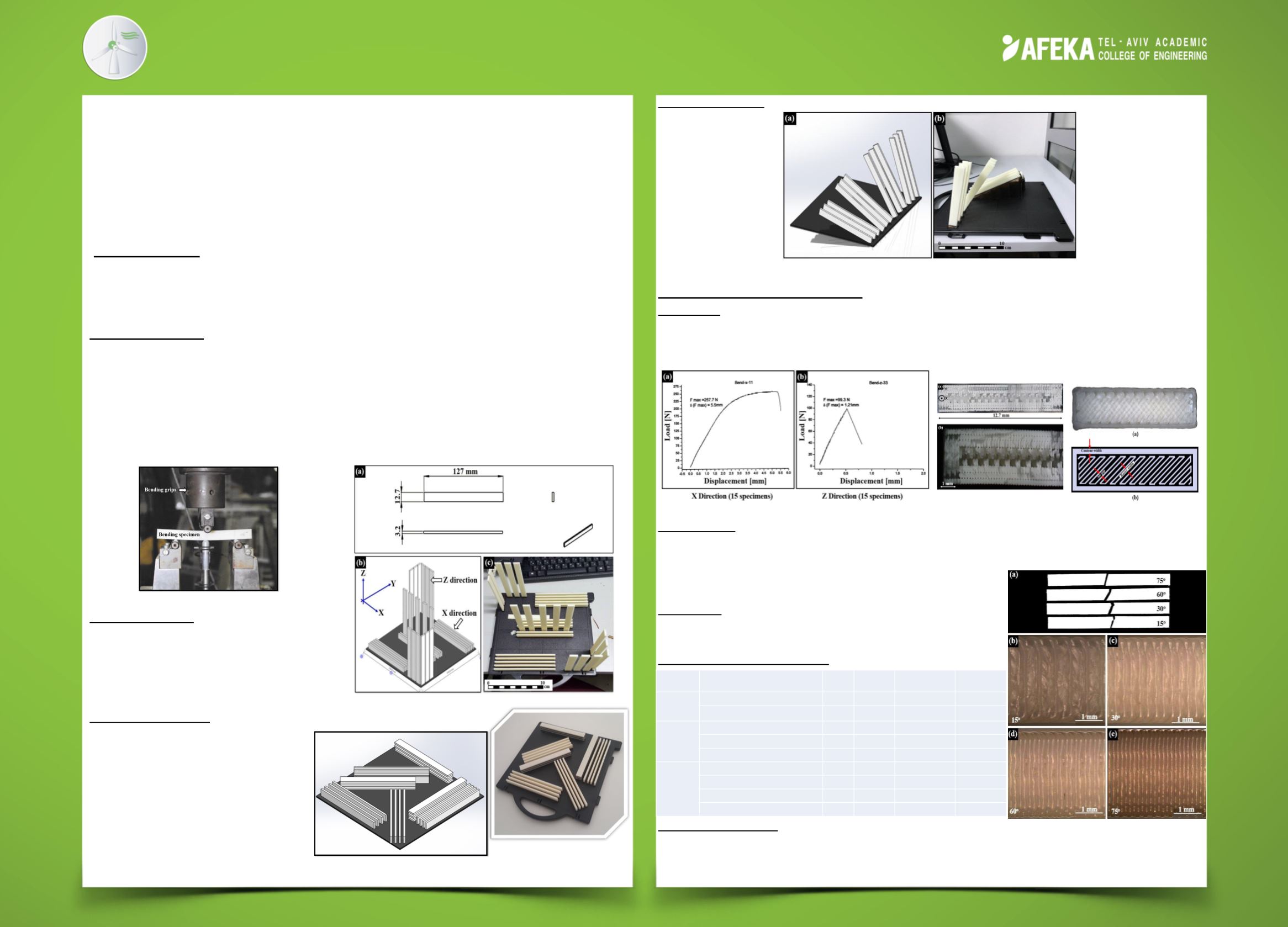
specimens were built in different angles to the XY plane: 15, 30, 60, and 75
degrees.
Figure 5.
Results and Conclusions
First tray :
Specimens built in the X-axis direction (the long axis of the specimens is directed
towards the tray`s X direction, 0 degrees relatively to the X-Y plane) exhibited higher strength
(maximum load and stress) values, by a factor of 2.5, compared to the strength measured on
bending specimens built in the Z direction (Fig. 6).
Figure 6.
Figure 7.
Second tray :
It was observed that there is no difference in bending properties obtained from
specimens at similar positions and from those printed in different heights along the Z-axis. Also,
no difference was observed in bending deflection specimens printed in the XY direction as
compared to those printed at 45 degrees to the main axes.
Third tray :
It is shown that high-angled specimens have
Smaller maximum bending stress and displacement values
comparing to low-angled bending specimens.
Summary of Bending Results :
Acknowledgements :
Figure 8.
Dr. Ashkenazi D. – Tel Aviv University; Rosenthal Y. – AFEKA; Tourgeman A. – NRCN; Berger A. –
HP; Adler A. – AFEKA.
The Purpose
This project explores possible effects of some 3D-printing parameters on the mechanical
properties in bending (Fig. 1) of ABS plus© in order to gain better understanding on this new
manufacturing method.
Max. Bending
Stress [Mpa]
Max. Displacement
in Bending [mm]
Max. Bending
Load [N]
number of
models
Parameters
58.2
4.5
250.4
15
Bild direction - X - 0 degrees
First
printing
23.4
1.2
100.6
15
Bild direction - Z - 90 degrees
46.7
4.1
201.0
16
Build direction - X/Y
Second
printing
49.8
5.3
214.3
6
printing 3 floors - 0/90 degrees
42.0
2.6
180.8
3
printing 3 floors - 45 degrees
57.4
4.5
247.0
3
printing angle degrees - 15 degrees
Third
printing
51.8
3.4
222.7
3
printing angle degrees - 30 degrees
34.5
1.8
148.3
3
printing angle degrees - 60 degrees
29.5
1.4
126.7
3
printing angle degrees - 75 degrees
Figure 2.