


 146-147 / 568

Design and implementation of a Printed Log
Periodic Dipole Antenna
Background
:
Log Periodic Dipole Array (LPDA) was invented by Dwight Isbell and
Raymond DuHamel at the University of Illinois in 1985.
The LPDA consists of a number of half – wave dipole driven elements,
each consisting of a pair of metal rods, each set tuned to a different
central frequency.
Project objectives
:
The project aims to design and implement 10 models of
LPDA applied to a microstrip printed technology (PLPDA)
operating in a frequency range of 1GHz-6GHz.
Methods
:
Given the desired gain of the antenna we will find the two
fundamental parameters
τ, σ
from the chart in figure 4:
τ
- The ratio between the lengths of neighboring dipoles and
the ratio between the dipoles distances from triangle apex.
σ
- The normalized spacing between neighboring dipoles
Now we follow the next formulas to calculate the
Antenna parameters
Michael Gudovsky
Advisor: Professor Ely Levine
Electrical Engineering
Now we follow the next formulas to calculate the
Antenna parameters
The opening angle :
= 2
−1
(
1−
4
)
.
Number of antenna elements :
= 1 +
(
)
(
1
)
The longest dipole
1
is determined by the lowest frequency:
1
= 1000 ×
2×
The other dipoles length is calculated by the ratio :
+1
= ×
The spacing of the longest dipole from the triangle apex:
1
=
1
2 ( )
The other dipoles spacing is calculated by the ratio:
+1
= ×
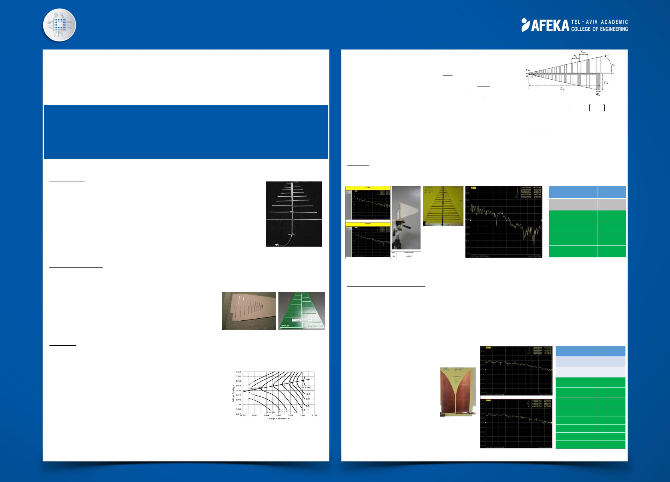
Results
:
The reference antenna with it’s gain, bandwidth and measurements is given in figure 5.
The best antenna model, regarding large bandwidth and high gain is shown in figure 6.
Summary and conclusions
:
The printed log periodic dipole antenna demands a very high precision in cutting the dipoles
to achieve a stable gain for all the desired frequency range.
The best LPDA I managed to achieve is operating in frequency range of 2-5[GHz] with a gain of
4[dB].
We can achieve much better results by building a tapper slot antenna (TSA)
With an exponential profile named “VIVALDI”
The antenna model in figure 8
is operating over a frequency
range of 3-10[GHz] and have a
high gain of 7[dB]
Following the opening of new frequency bands for wireless
communication the demand for wideband antennas increased.
The goal of this project is to design and implement of a log
periodic dipole antenna applied in printed circuit technology.
Figure 1: The first Log periodic array built by Isbell
Figure 2: The LPDA applied in a printed circuit technology
Figure 4: Typical gain values depending on the two fundamental parameters
Figure 3: The LPDA structure
Figure 5: Reference antenna
Figure 7: My model power measurement
Gain [dB]
Frequency [GHz]
0
1
3
2
4
3
4
4
4
5
Table 1: Antenna calculated gain
Figure 6: LPDA antenna model
Figure 9: My VIVALDI model power measurement
Gain [dB]
Frequency [GHz]
0
1
2
2
7
3
7
4
7
5
7
6
7
7
7
8
7
9
7
10
Table 2: VIVALDI Antenna calculated gain
Figure 8: My VIVALDI model